Nice Tips About Why Is The Voltage Not Same In A Series Circuit

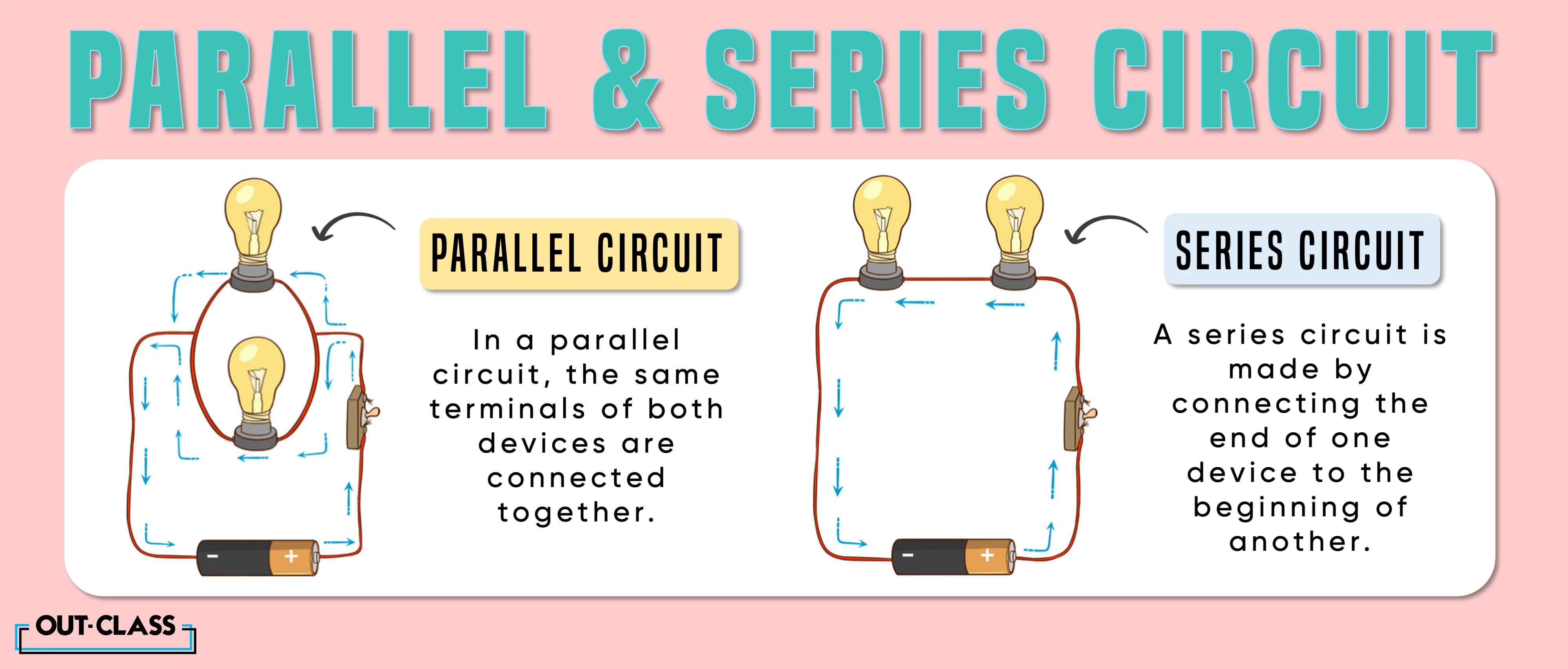
Basic Series Circuit Diagram
Understanding Voltage Drops in Series Circuits
1. What's Up With Uneven Voltage?
Ever wondered why the voltage you measure across different light bulbs in a series Christmas light strand isn't the same? It's not some magical electrical gremlin at work, I promise! The simple explanation is that each component in a series circuit — whether it's a resistor, a light bulb, or even a particularly stubborn paperclip if you're feeling adventurous — uses up some of the electrical potential energy, which we measure as voltage.
Think of it like this: imagine you're pouring water (representing electricity) down a series of waterfalls (the components). Each waterfall diminishes the water's potential energy before it reaches the next one. By the time the water reaches the last waterfall, it has a lot less potential energy left. In an electrical circuit, this "potential energy" is voltage, and it decreases as it passes through each element.
The key is the term "series." In a series circuit, the current (the flow of electrons) has only one path to follow. This means the same amount of current flows through every component. But, because each component offers some resistance to that flow, voltage gets "dropped" along the way. It's like everyone in a relay race has to run the same distance, but some runners use more energy doing it than others.
So, if you have, say, three resistors connected in series, the total voltage supplied by the battery gets divided amongst them. The amount of voltage each resistor gets depends on its resistance value. Higher resistance means a larger voltage drop. Think of a bigger rock in our waterfall analogy — it's going to cause a bigger splash and reduce the water's energy more!

Resistors Calculating The Voltage Dropped In A Series/parallel
Resistance
2. Why Resistance Matters
Resistance is absolutely the star of this particular show. It's the opposition to the flow of electrical current. Everything has some resistance, even wires (though usually very little). Components like resistors are designed to have specific resistance values. This is measured in Ohms (), named after Georg Ohm, the guy who figured out the relationship between voltage, current, and resistance.
Ohm's Law (V = IR) is your best friend here. It states that voltage (V) is equal to current (I) multiplied by resistance (R). If the current (I) is the same throughout a series circuit (which it is!), then the voltage drop across a component (V) is directly proportional to its resistance (R). Double the resistance, double the voltage drop!
Let's say you have two resistors in series. One is 10 Ohms and the other is 20 Ohms. The 20-Ohm resistor will have twice the voltage drop as the 10-Ohm resistor. It's hogging the voltage because it's offering more resistance to the current flow. It's the electrical equivalent of a really stubborn gate that requires more effort to push open.
This is why voltage isn't the same everywhere. It's not a defect; it's a fundamental property of how series circuits work. The varying resistances of the components cause the voltage to be divided unevenly. Consider light bulbs again. A bulb with a higher wattage (which generally means lower resistance) will have a smaller voltage drop compared to a bulb with a lower wattage (and thus higher resistance).

Why Is The Voltage Drop Same In A Parallel Circuit Diagram
How to Calculate Voltage Drops
3. Math Time (But Don't Panic!)
Okay, I know math might not be everyone's favorite activity, but calculating voltage drops isn't as scary as it sounds. Remember Ohm's Law: V = IR. To find the voltage drop across a specific resistor in a series circuit, you need to know two things: the current flowing through the circuit and the resistance of that particular resistor.
First, you need to figure out the total resistance of the series circuit. To do this, simply add up the resistances of all the components. So, if you have three resistors with values of 10 Ohms, 20 Ohms, and 30 Ohms, the total resistance is 10 + 20 + 30 = 60 Ohms.
Next, determine the current flowing through the circuit. You can use Ohm's Law again, but this time using the total voltage supplied by the battery (Vs) and the total resistance (Rt). So, I = Vs / Rt. If the battery is supplying 12 volts, then the current is I = 12 / 60 = 0.2 Amps.
Now, you can calculate the voltage drop across each individual resistor. For the 10-Ohm resistor, the voltage drop is V = (0.2 Amps) (10 Ohms) = 2 Volts. For the 20-Ohm resistor, it's V = (0.2 Amps) (20 Ohms) = 4 Volts. And for the 30-Ohm resistor, it's V = (0.2 Amps) (30 Ohms) = 6 Volts. Notice that these voltage drops add up to the total voltage supplied by the battery (2 + 4 + 6 = 12 Volts). That's how you know you've done it right! Think of it as distributing the voltage "pie" amongst the resistors based on their resistance "size."
Real-World Examples and Applications
4. Voltage Drops in Action
Series circuits might seem like abstract concepts, but they show up everywhere. Christmas lights are a classic example. Each tiny bulb acts as a resistor, and the voltage from the wall outlet gets divided among them. If one bulb burns out, it breaks the circuit, and all the lights go out. (That's why finding the bad bulb is such a pain!) The high resistance of the broken bulb's filament causes the voltage to redistribute, potentially stressing the remaining bulbs.
Another example is simple voltage dividers, which are often used in electronics to create a specific voltage level from a higher voltage source. These circuits use two or more resistors in series to "tap off" a desired voltage. The voltage at the point between the resistors is a fraction of the input voltage, determined by the ratio of the resistors.
Even inside your computer or phone, series circuits are used for various purposes, such as regulating the current flowing through LEDs or other components. Understanding voltage drops is essential for designing and troubleshooting these electronic systems. Engineers need to calculate the voltage and current requirements of each component to ensure proper operation and prevent damage.
Consider a string of LEDs connected in series. Each LED has a specific forward voltage drop. If the supply voltage is too low, the LEDs won't light up. If the supply voltage is too high (without proper current limiting), the LEDs could overheat and burn out. Careful calculations are needed to select the correct resistors to limit the current and ensure that each LED receives the appropriate voltage.
Troubleshooting Voltage Problems
5. Fixing Circuit Issues
If you're working with a series circuit and the voltage drops aren't what you expect, there are a few things to check. First, make sure all the connections are solid. Loose connections can add unexpected resistance, leading to inaccurate voltage readings.
Next, verify the resistance values of the components. Resistors can sometimes drift from their marked values, especially if they've been overheated. Use a multimeter to measure the actual resistance of each component. If a resistor is significantly different from its expected value, it needs to be replaced.
Also, check for short circuits. A short circuit occurs when current bypasses a component, taking a shorter path with less resistance. This can cause excessive current to flow through other parts of the circuit, leading to voltage drops that are much lower than expected. Look for any wires that might be touching each other or any components that appear damaged.
Finally, remember that voltage is always measured across* a component. If you're measuring voltage from a single point to ground, you're not measuring the voltage drop across that component. Make sure you're placing the multimeter probes on either side of the component to get an accurate reading. Think of it like measuring the difference in height between the top and bottom of a waterfall, rather than measuring the height from the ground to the top of the waterfall.

Series Vs Parallel Circuit Diagram
FAQ
6. Your Burning Questions Answered
Still a little confused? Here are some frequently asked questions that might help clarify things.
Q: Why does the current stay the same in a series circuit?
A: Because there's only one path for the electrons to flow. It's like a single-lane road. All the cars (electrons) have to follow the same route.
Q: What happens if one resistor in a series circuit burns out?
A: The circuit is broken, and no current flows. It's like a bridge collapsing on that single-lane road — traffic stops completely.
Q: How can I increase the voltage drop across a specific resistor?
A: Either increase the resistance of that resistor or increase the current flowing through the circuit. Remember Ohm's Law: V = IR!

